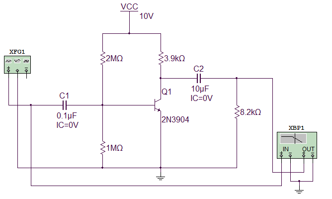

The two denominator terms have similar behavior, except for the fact that the slope is −π/4 and that the straight line with slope −π/4 rad/decade extends between the frequencies 0.1ω 2 and 10ω 2, and 0.1ω 3 and 10ω 3, respectively.įigure 3 depicts the asymptotic approximations of the individual factors in equation 13, with the magnitude factors shown in Figure 3(a) and the phase factors in Figure 3(b). The numerator first-order term, on the other hand, can be approximated, that is, by drawing a straight line starting at 0.1ω 1 =0.5, with slope +π/4rad/decade (positive because this is a numerator factor) and ending at 10ω 1 = 50, where the asymptote +π/2 is reached. If we now consider the phase response portion of equation 13, we recognize that the first term, the phase angle of the constant, is always zero. You see that the individual factors are very easy to plot by inspection once the frequency response function has been normalized in the form of equation 9. The numerator term, with a 3-dB frequency ω 1 = 5, is expressed in the form of the first-order Bode plot of Figure 1(a), except for the fact that the slope of the line leaving the zero axis at ω 1= 5 is +20 dB/decade each of the two denominator factors is similarly plotted as lines of slope −20 dB/decade, departing the zero axis at ω 2 = 10 and ω 3 = 100. Finally, implement the algorithm on LabView/Multisim for future. The constant corresponds to the value −46 dB, plotted in Figure 3(a) as a line of zero slope. Then apply the algorithm on sophisticated circuit model.

#Bode plot multisim how to

The toolbox you see on your right hand side is a Instruments toolbox.It contains equipments such as Now you have finished your installation.
#Bode plot multisim trial
Then open your Multisim Software,Now you have got 2 years trial period of use.Click on Evaluate.This will open your multisim simulation software.Go to start->All Programs->National Instruments->Circuit Design Suit->Multisim.Then click Restart to complete your installation.After the installation is complete click next>.After that the installation will start.Click on I accept Lisence agreements and then click next>.Set your Destination Directory for installation and click on next>.
#Bode plot multisim install


 0 kommentar(er)
